A ground source heat pump is functionally a mechanical link that uses the earth as an infinitely-scalable heat source or heat sink.
Connecting to this source requires a Ground Heat Exchanger (GHX), which can be configured as a Closed-Loop (horizontal, vertical, or pond) or an Open-Loop (well-water) system. The choice of configuration depends entirely on local Lithology, available land area, and drilling costs.
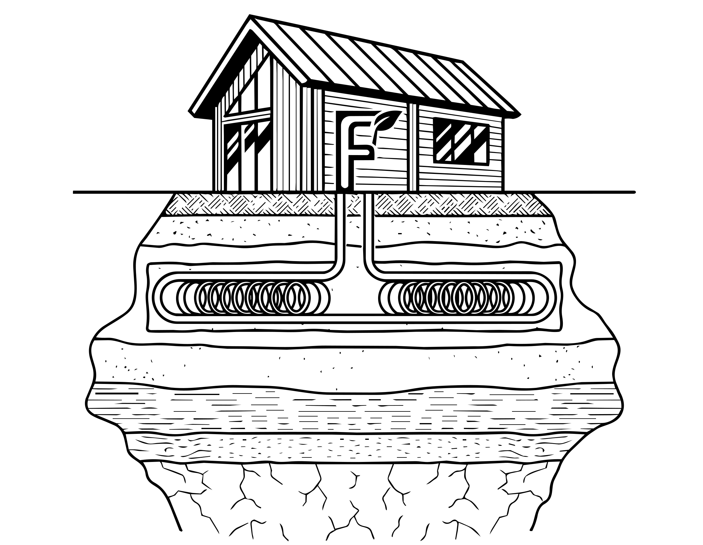
This configuration is usually the most cost effective but can only be used when adequate yard space is available and when trenches are easy to dig. To install a Horizontal Loop, workers utilize trenchers or backhoes to dig a Horizontal Trench 5-8 feet below ground and then install a series of HDPE pipes that comprise the geothermal heat exchanger. They will then backfill the trench, taking care not to allow sharp rocks or debris to damage the pipes.
A common practice is to coil the pipe into a Slinky shape to fit the loopfield in a smaller area. While doing this reduces the amount of land area needed, it will require installation of more pipe. When retrofitting a home with a GSHP system, a horizontal ground loop installation may pose more problems because landscaping will have already been completed.
However, new types of horizontal boring equipment are making it possible to retrofit geothermal heat pump systems into existing homes with minimal disturbance to lawns. Horizontal Bore (directional boring, HDD) machines can even allow entire systems to be installed under existing buildings or driveways.
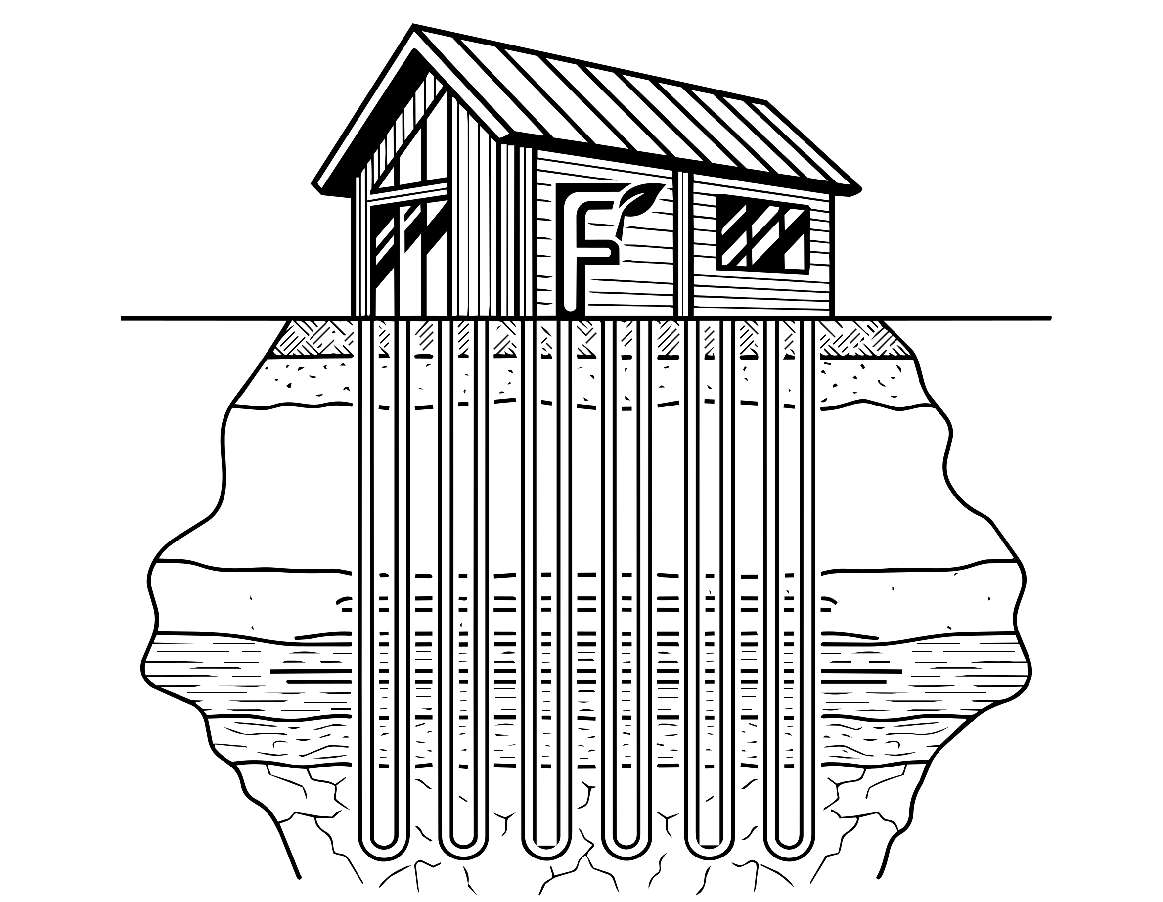
This configuration is ideal for homes where yard space is limited, when rock formations are very close to the surface, or retrofit applications where minimum disruption of the landscaping is desired.
To install a Vertical Loop, a contractor will use well-drilling equipment to bore a 5-6 inch diameter Vertical Bore in the ground 150-450 feet deep. Next, a single pipe loop with a U-Bend at the bottom is inserted in the hole. After the pipe is inserted, the hole will be grouted, filling it from bottom to top.
The function of the grout is to ensure contact between pipe and the earth to promote heat transfer as well as to seal the hole off from any Aquifers or groundwater supplies that may have been penetrated during the drilling process. Protecting the deep earth environment with a proper grouting material is just as important as providing heat transfer between the piping system and the surrounding earth. Vertical loops are generally more expensive to install, but require less piping and less land area than Horizontal Loops.
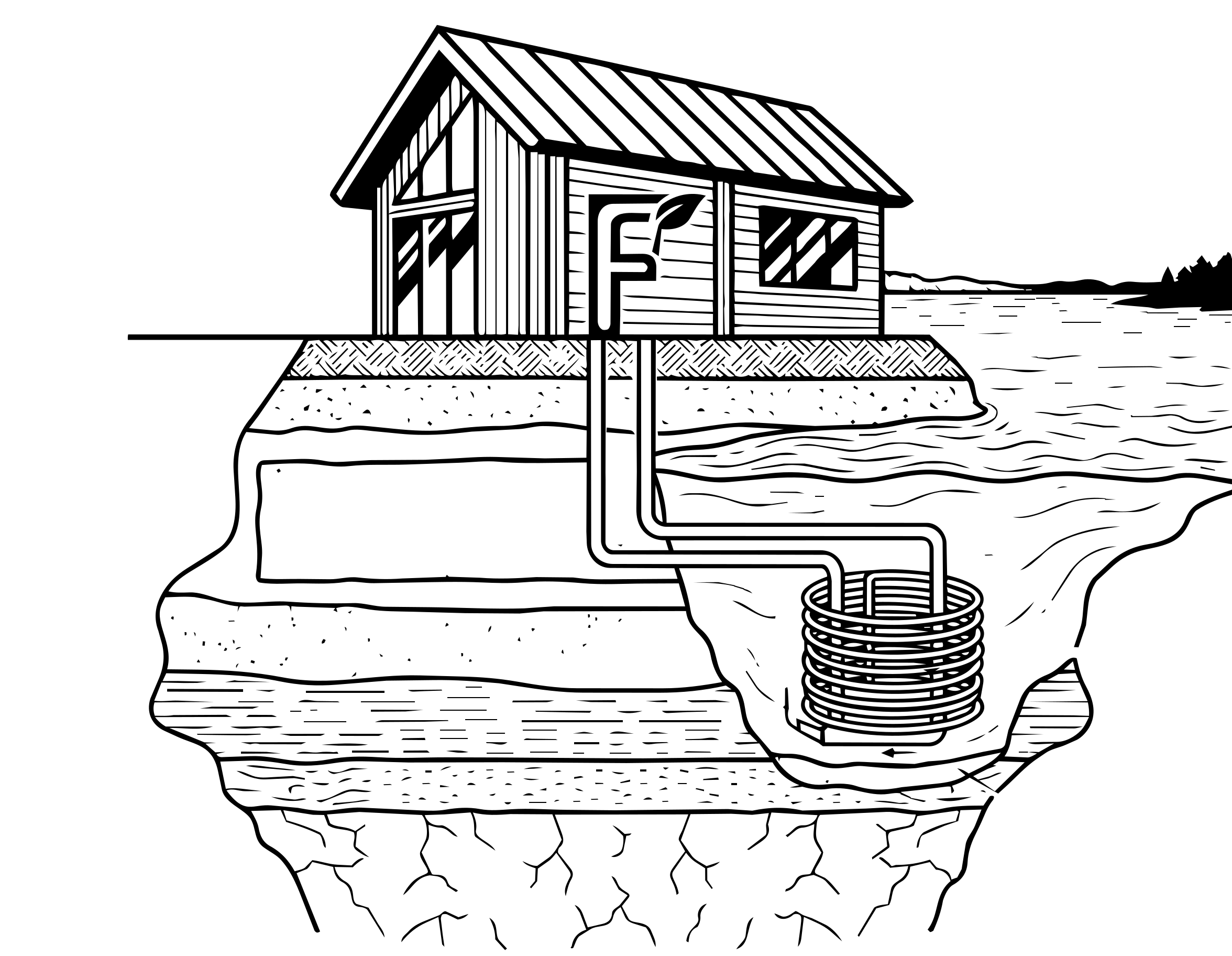
If a home is near a sufficiently-sized body of surface water, such as a pond or lake, this configuration may be the most economical. To install a Pond Loop, a contractor will simply place a Submerged Heat Exchanger — an adequately-sized piping system — in the body of water.
Similar to a horizontal system, it is common practice to coil the pipe in a Slinky shape to fit more pipe in a smaller area. Fluid circulates through HDPE piping in a Closed-Loop system just as it does in horizontal and vertical ground loops. Experts recommend using a pond loop only if the water level never drops below six to eight feet at its lowest point to ensure sufficient heat-transfer capability.
While pond loops work very well in cooling-dominant climates, caution must be used when installing these systems in heating-dominant climates. If properly installed, pond heat exchangers will not adversely impact the surrounding aquatic system.
Each loop in a vertical, horizontal or pond loop configuration is connected to a horizontal piping system in a parallel arrangement. This horizontal piping system is referred to as Header Piping (supply-return piping, S-R piping). Header piping will be buried 5-6 feet underground to be brought into the home.
The purpose of the header piping is to carry the circulating fluid in the system from the loopfield to the geothermal heat pump inside the building. When header piping is brought in close proximity to water or sewer lines, insulation must be placed between them prevent the water/sewer lines from freezing.
To ensure satisfactory results, a ground heat exchanger should be installed by an IGSHPA accredited installer. This will ensure that your contractor will have all of the necessary tools and resources to install a properly-sized GHX.
Open-Loop geothermal systems extract water directly out of a water well or pond and run it through the water-refrigerant heat exchanger in the GSHP unit. After the transfer of heat between the extracted water and heat pump takes place, the water is then expelled back into a well, into a pond, or into a drainage ditch depending on local codes.
This type of ground connection method is used less frequently, but may be employed cost-effectively if ground water is plentiful. Open loop systems are the simplest to install and have been used successfully for decades in areas where local codes permit. In this type of system, ground water from an Aquifer is piped directly from a well to the building where it transfers its heat to a GSHP.
After the water leaves the building, it is expelled back into the same aquifer via a second well, called a discharge well, located a suitable distance from the first. Local environmental officials should be consulted whenever an open loop system is being considered.
Because open-loop systems utilize water on a "once through" basis, they are often referred to as "Pump and Dump" systems. The performance of the GSHP system may degrade over time if Water Quality issues are present (high mineral or dissolved solids content, etc) or if the water supply diminishes for any reason.
[ Awaiting Brand-Neutral Vector Graphic ]
Standing Column Wells have become an established technology in some regions, especially the northeastern United States. Standing column wells are typically six inches in diameter and may be as much as 1500 feet deep.
Temperate water from the bottom of the well is withdrawn, circulated through the heat pump’s water-refrigerant heat exchanger and returned to the top of the water column in the same well. Usually, the well also serves to provide potable water.
However, ground water must be plentiful for a standing well system to operate effectively. If the standing well is installed where the water table is too deep, pumping may become cost prohibitive. Under normal circumstances, the water diverted for building (potable) use is replaced by constant-temperature ground water which makes the system act like a true Open-Loop system.
If the well-water temperature climbs too high or drops too low, water can be discharged through a controlled Bleed to allow ground water to restore the well water temperature to the normal operating range. Permitting conditions for discharging the bleed water vary from locality to locality.
Copyright © 2012 by Verdant Labworks. All rights reserved.
To model these design configurations effectively in your engineering workflows, visit FORB.